Designing an 8 amp, 75 V linear regulator.
So amishx64 @ Reddit said they wanted a medium voltage, high amp regulator. Specifically, something to regulate 76 volts down to 70, and do so at a current of 8 amps(!).
In electronics, "build it yourself from discrete components" is almost never the right answer. There's almost always something out there you can buy to do the job for you. And it's usually better engineered, often cheaper, and nearly always safer than it would be if you built it yourself.
There are plenty of appnotes out there that show various ways to extend the input voltage handling of a standard regulator. For instance, by using a zener diode to let the regulator's ground "float" a few volts below the input voltage. That way, the transistors inside the regulator are never exposed to more than a few volts of differential voltage, and everything is fine. There are even more exotic methods too, like this appnote from Linear Tech that suggests (among other things) using a vacuum tube! (See page 7.)
However, due to the with very high current requirement and much higher than normal voltage, this request struck me as one where you might actually not be able to find a premade regulator that would do the job. So I decided to try and design my own.
First big decision: Since this person only wants to drop a few volts, a linear regulator is not unreasonable. Linear regs are usually frowned on at large current levels, because I*V power losses quickly dominate. However, these losses depend on V, and if you're only dropping a few volts, the losses are not as bad as you might expect. Also linear regs are simple to build.
Second big decision: use MOSFETs. Using BJTs at these kind of current levels is really only for people who enjoy using their electronics as space heaters. Also, MOSFETs can be paralleled easily, with no danger of thermal runaway or one device trying to supply the entire load itself. Given the kind of voltages involved these will probably need to be P-channel MOSFETs, which are turned on by pulling the gate voltage low with respect to source. A N-channel MOSFET, on the other hand, needs its gate pulled high with respect to source. With an output voltage of 70 volts, an N-channel MOSFET's gate might have to be pulled up to 85V or higher in order to make it conduct 8 amps. And I don't feel like building a charge pump into this thing. ;]
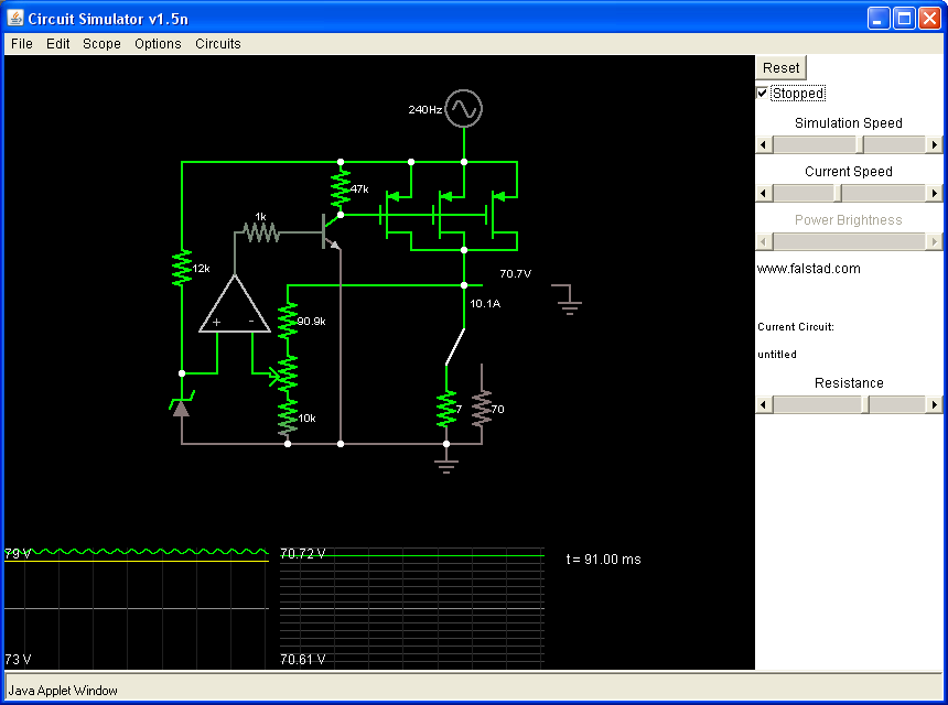
That decided, now it was mainly just a question of using the classic negative-feedback regulator architecture and adapting it to P-channel MOSFETs. I'm pretty pleased with the resulting circuit:
Falstad Circuit Sim code: http://www.gully.org/~mackys/circuits/linreg-opamp.txt
This is actually a lot simpler than it looks. First, the regulated voltage coming out of the three P-channel MOSFETs at top-right is run through a "divide by ten" resistive voltage divider, to bring it down to a level the opamp can handle. The potentiometer allows mild tweaking of the voltage divider's output. The other input of the opamp is a constant 7.2 V voltage, created by the 7.2 V zener diode. (Said zener being biased to the proper 5 mA of reverse current by the 12k resistor above it.)
Both voltages are fed to the opamp, which compares them. If the (regulated voltage / 10) is less than about 7.2 V, the opamp increases its output voltage, consequently turning on the NPN transistor attached to the MOSFETs' gates. This allows current to flow from the MOSFETs' gates to ground, decreasing the gate voltage. Since these are P-channel MOSFETs that turns them on, and allows more current to flow through them and into the load. Consequently, the regulated voltage rises.
On the other hand, when the regulated voltage is too high, the opamp decreases its output voltage, turning off the NPN, and so current coming in through the 47k resistor begins to drag the MOSFETs' gate voltages up. This turns the MOSFETs off, so they allow less current into the load, and the regulated voltage falls.
The circuit works very well, and regulation is quite good. Differences in load current have no discernible effect on the regulated voltage in simulation. The circuit also does a pretty good job nulling out fluctuations in the input voltage. If you look at the graphs, the left one shows the input voltage, which is a 240 Hz sine wave that varies between 73 and 79 V. The output voltage is on the right graph, and it wobbles less than one tenth of a volt - even as the regulator is supplying 10 amps!
Most of this wobble is due to the simplicity of the zener diode voltage source, which is directly connected to the fluctuating input voltage via the 12k resistor. The slight fluctuations in current through the 12k resistor cause a slight fluctuation in voltage across the zener. One solution is to use a constant current source instead of a resistor. You could certainly build a two-transitor current mirror to do this, but personally I prefer the JFET constant current source. It's extremely simple and it works. And they're available as off-the-shelf single components, with the JFET and resistor integrated into a single diode-like package. They call them "constant current diodes". Take a look:
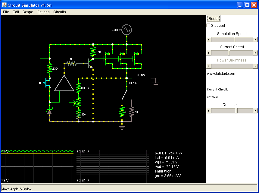
With the 12k resistor replaced with a constant current device, the regulated voltage does not fluctuate at all. Well worth the single additional JFET!
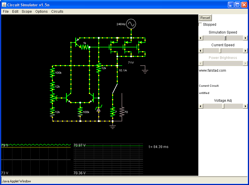
Finally: have you heard people say, "Anything you can do with an opamp, you can in theory also do with a differential transistor pair"? Well, check it out:
Falstad Circuit Sim code: http://www.gully.org/~mackys/circuits/linreg-ltp.txt
A classic long-tailed pair, though simplified a little bit - I said to hell with the collector resistors. The way this works is pretty much like the opamp circuit, though note the zener and 10:1 voltage divider have switched sides. When the regulated voltage gets too high, it turns on the left side NPN, which turns on the PNP at the top. The PNP dumps current into the MOSFETs' gates, raising their voltage and turning them off. On the other hand, when the regulated voltage is too low, the right side NPN turns on, and steals current from the MOSFETs' gates, lowering their voltage and turning them on.
microsofat @ Reddit points out that the above explanation is both confusing and wrong. (Hence why it's been struck out.) A better explanation is that when the input voltage is constant, the PNP lets a constant amount of current into the MOSFETs' gates, while the right side NPN lets a constant amount out. This maintains the gate voltage at a constant value. When the regulated voltage goes up, the left side NPN turns on the PNP more, allowing more current into the gates than is going out. This increases the gate voltage, turning the MOSFETs off. When the regulated voltage goes down, the opposite happens.
Again, there is some fluctuation caused by the input voltage ripple messing with the zener. But the same JFET constant-current fix works again, and again slaughters any interference from input voltage fluctuations.
The position of the 1k resistor may seem strange. I wanted to put it on the emitter of the PNP, so it would limit both base current and collector current. But if you do that and then hit the Reset button, Falstad Sim pukes and claims either "nan/infinite matrix" or "convergence failed". In the real circuit, I would put the 1k on the PNP's emitter.
Edit 2012/01/03: Seems like there's always someone calling me out for daring to use Falstad Circuit Sim to do "serious" electrical engineering. Personally, I feel that people who criticize on this basis are basically just butt-hurt that I didn't use a gold-plated hammer. Also, I find intellectual snobbery just as annoying as the monetary kind. :P
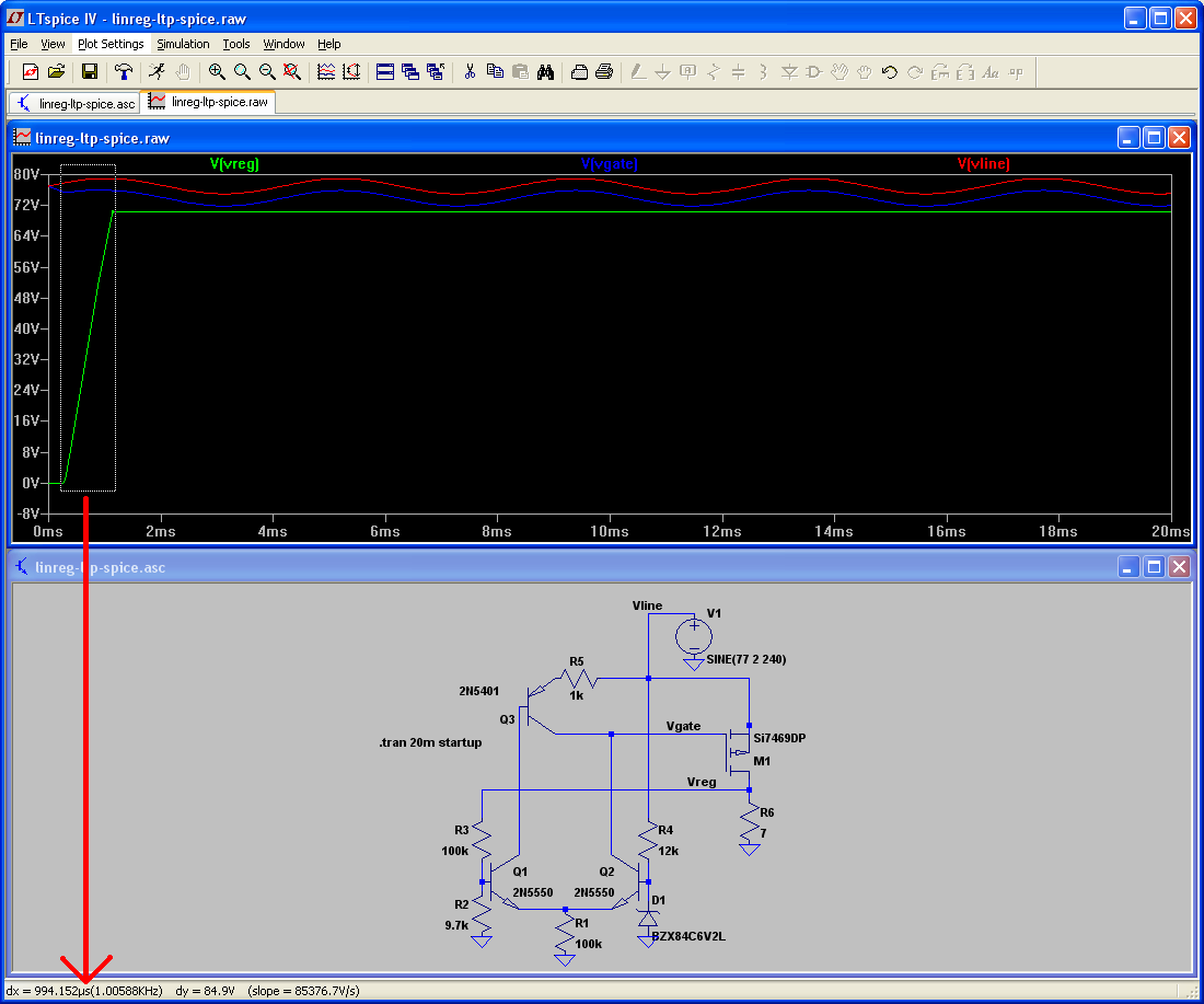
So just for aedane @ Reddit, here is the same circuit rebuilt in LTSpiceIV, an industrial grade electronics simulator:
LTSpiceIV sim code: http://www.gully.org/~mackys/circuits/linreg-ltp-spice.asc
You'll notice that I had to mess with the voltage divider. That's because LTSpiceIV doesn't come with a 7.2V zener, so I had to use a 6.2V one and change the voltage divider accordingly. (Score one for Falstad sim, which allows you to make an arbitrary voltage zener very easily.)
Another thing you'll notice is that it takes the regulated voltage a pretty long time (almost a full millisecond) to come up to full value at startup. This is of course because the 100k resistor on the long-tailed pair limits the amount of current that can be sucked out of the MOSFETs' gates. The easy and obvious fix is to add another PNP, controlled by the other transistor in the pair:
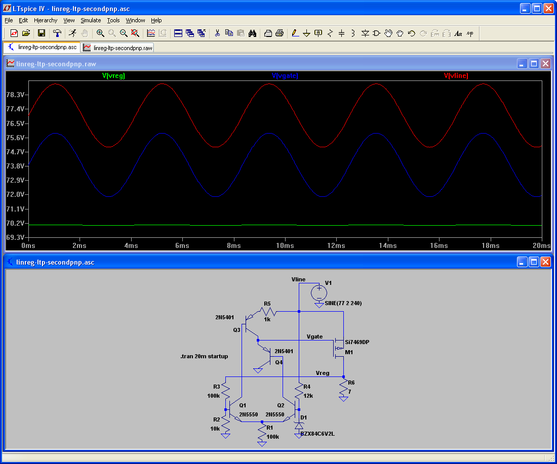
LTSpiceIV sim code: http://www.gully.org/~mackys/circuits/linreg-ltp-secondpnp.asc
That picture pretty much says it all. I have nothing further to add as far as the functionality of the circuit goes.
However, a word on transistor selection: I chose the BJTs I did because they're all capable of handling 150 V. But there are also much more common transistors (like the 80V 2n3019 NPN, and 65V BC556B PNP) that are likely to work fine. Same deal with the Si7469DP - mainly chosen because it was a low-Rds(on) P-channel MOSFET that could handle 80V. But again, you can probably find a cheaper and more common P-channel MOSFET that will work just fine.
Lastly: I want to give credit to tekscopes @ Reddit for pointing out that a 6V regulation drop at 8A will guarantee a total power dissipation in the MOSFET(s) of 48W! For reference, a standard TO-220 package will usually be able to handle about 2W max without additional heat-sinking. So if you actually build the circuit, do not skimp on the heat sinks on the MOSFETs!
So there you have it. An 75V, 8A linear regulator built from four or five transistors (depending on how many P-channel MOSFETs you need), a zener diode, and some resistors. WARNING: I haven't actually built these, so they may not work as well in reality as they do in sim. If you end up building one of them, let me know how it goes!